Views: 0 Author: Site Editor Publish Time: 2025-07-21 Origin: Site
■ 1.Design Principle
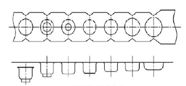
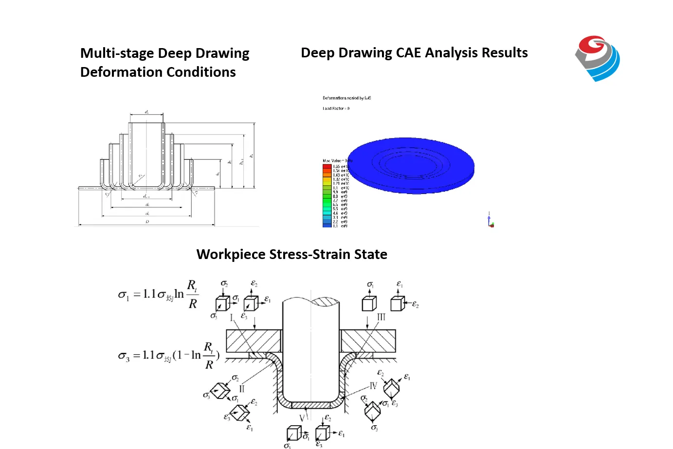
Through single or multiple passes of deformation during forming, the stainless steel blank gradually acquires the desired dimensions and shape across continuous workstations. Utilizing a press and die, pressure is applied to the stainless steel sheet, causing forming deformation to achieve the transformation from flat material into a stretched part with specific geometry and dimensions.

Stretching Process Diagram
■ 2.Desgin point
Material feature analysis:Conduct an in-depth study of stainless steel material parameters, including plasticity, elongation rate, strain hardening exponent (n-value), and normal anisotropy coefficient (r-value). These parameters directly influence the material's flow capability, thinning tendency, and springback magnitude. Simultaneously, evaluate the material's surface condition to select appropriate lubricants, thereby reducing friction and preventing scratches during stretching.
■ 3.Process plan Formulation
Drawing Coefficients & Stages
Precisely determine the drawing coefficient for each pass (m = d/D, where *d* = post-drawing diameter, D = pre-drawing diameter), strictly adhering to the material’s allowable limits.Insufficient stages may cause material cracking.
Excessive stages waste stations, reduce efficiency, and increase costs.Process Layout Optimization:Rationally distribute deformation (e.g., diameter reduction, thinning) across passes to ensure uniform deformation and controlled stress, avoiding localized cracking or wrinkling.
For deep-drawn parts, prioritize a "stepwise" drawing strategy (e.g., tapered or rounded punch profiles) to guide material flow progressively and mitigate cracking risks.
Strip Carrier Design
Strength and Stability: Ensure the strip material has sufficient strength and rigidity during feeding, particularly in later stages, to resist drawing forces and prevent warping deformation or fracture.Carrier Bridge (Web) Design: Optimize the width and placement of carrier bridges to achieve the best balance between feeding stability and material utilization efficiency.
Punch/Die Desgin
Radius Design:Die Entry Radius (Rd) & Punch Tip Radius (Rp) are critical parameters.Rd too small → Increased flow resistance, risk of cracking or excessive thinning.Rd too large → Promotes inner wrinkling.Rp affects material conformity and bottom strength, requiring careful calculation based on material type, thickness, and process stage.Clearance Control:Single-side clearance = (1.1–1.3) × material thickness (t).Too small → High friction/wear, material scratching.Too large → Poor wall quality, wrinkling risk.Surface Finish:Forming zones (especially die radius & punch working area) must achieve high smoothness (Ra ≤ 0.2μm).Surface treatments (e.g., hard chrome plating, TD coating, PVD) reduce friction, resist wear, and prevent scratches.
Structural Strength
Punches/dies must have sufficient rigidity to withstand forming forces without elastic deformation (which causes precision loss or cracking).Modular (split) designs are recommended for complex geometries or high loads.

Blank Holder Design
The blank holder must deliver sufficient and uniform pressure. Insufficient force causes flange wrinkling, while excessive force increases flow resistance leading to fractures. Nitrogen springs or polyurethane springs are typically used to provide stable pressure.Blank Holder Surface Matching:The blank holder's pressing surface must precisely align with the die surface to ensure even force distribution across the entire blanking zone. Limit pillars are often designed to control the closing height accurately. Additionally, the pressing surface requires high-gloss finishing.
Positioning & Guidance System
High-Precision Guide Pillars & Bushings:Made of high-rigidity, wear-resistant materials (e.g., SUJ2 bearing steel) to ensure precise die alignment in high-speed stamping.Protects punch/die edges and maintains forming accuracy.Internal Guide Pillars/Bushings:Added at critical stations (e.g., drawing, sizing) for enhanced local alignment.Feeding & Positioning:Pilot pins, side stops ensure consistent strip positioning at each station.Design considerations:Pilot pin diameter, length, and fit tolerance must be optimized.Side stops prevent material misalignment during feeding
■ Manufacturing Process
Stamping Die Material Selection: Based on operational requirements and performance characteristics, appropriate die steel materials such as Cr12MoV and SKD11 are selected. These materials exhibit high hardness, superior strength, excellent wear resistance, and toughness, meeting the working demands of stainless steel progressive drawing dies.
Machining Process: Advanced manufacturing techniques—including CNC machining, EDM (electrical discharge machining), and wire cutting—are employed to ensure machining precision and surface quality. For complex die structures, multi-axis machining centers may be utilized to achieve high-precision forming.
Surface Treatment: To enhance wear resistance, corrosion resistance, and release performance, die surfaces undergo specialized treatments such as hard chrome plating, nitriding, or PVD coating. These processes form a hard, smooth protective layer that reduces friction between the die and material, significantly extending tool life.

Disassembled Diagram of Progressive Die
■ GreeDaikinMold Advantages
1. Improved Production Efficiency: The process enables multiple drawing operations to be completed in one continuous cycle, eliminating the frequent loading/unloading and die adjustments required in traditional single/double-action deep drawing, significantly boosting production efficiency.
2. Enhanced Product Quality: Precise control of drawing parameters and optimized die design effectively prevents defects such as wrinkling, cracking, and springback, ensuring superior dimensional accuracy and surface finish.
3. Cost Reduction: Progressive drawing dies facilitate automated production, reducing labor costs, while higher material utilization and extended tool life lower material expenses and die replacement costs.
■ Application Fields
Widely used in automotive manufacturing (e.g., body panels, chassis components), aerospace (e.g., engine housings), electronics (e.g., device enclosures), new energy (e.g., battery casings), and consumer goods (e.g., stainless steel tableware) industries.
content is empty!
ZHUHAI GREE DAIKIN PRECISION MOLD CO., LTD.