Views: 0 Author: Site Editor Publish Time: 2025-10-07 Origin: Site
■ Mold design
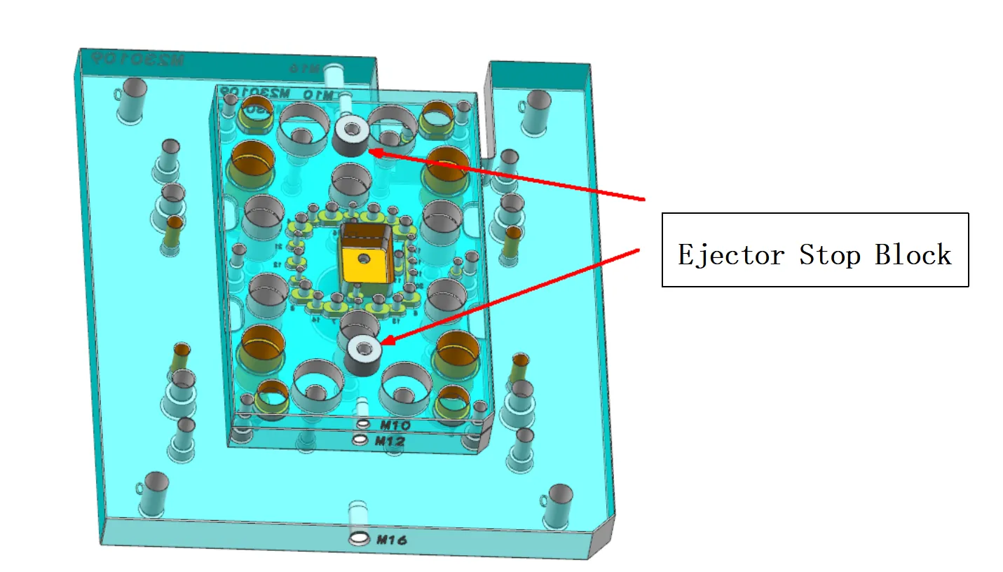
Molds with either the length or width of the mold base exceeding 800mm (inclusive) must be designed with at least four limit blocks. In other cases, the number of limit blocks may be adjusted according to the number of ejector pin holes, but shall not be fewer than the number of ejector pin holes.
Ensure symmetrical arrangement.
In general, the limit blocks should be positioned directly above or near the ejector pin holes.
■ Design Method
The limit blocks shall be directly designed into the 3D mold structure and uniformly assembled on the ejector plate (as shown in the figure below). They are to be machined directly by the mold base manufacturer.

■ The dimension of the stopper
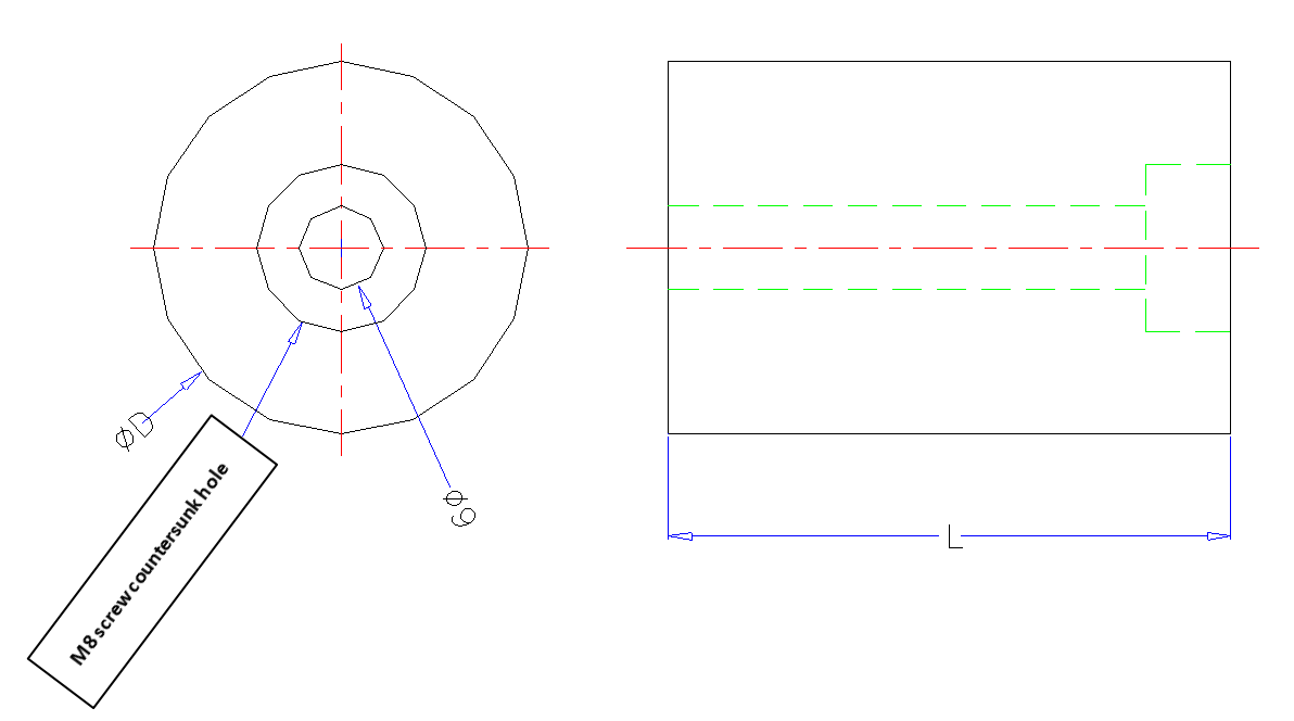
Outer diameter | Use screw | Long | Notice |
φ30 | M8 | According to the actual situation | Die plate width<400 mm |
φ50 | M8 | According to the actual situation | Die plate width ≥400 mm |

When determining their placement, flexible adjustments must be made to ensure there is no interference with ejector pins, ejector sleeves, angle lifters, support pillars, spring-loaded rods, or ejector plate guide pillars.
ZHUHAI GREE DAIKIN PRECISION MOLD CO., LTD.